On This Page
Give the capture team current elevations, building dimensions, facade materials,
previous findings, and the intended inspection scope. Agree on names for
elevations, floors, bays, and individual panels so the photographer, reviewer,
and maintenance contractor use the same locations. Mark projections, recessed
surfaces, adjoining structures, and areas that cannot be photographed from the
proposed positions.
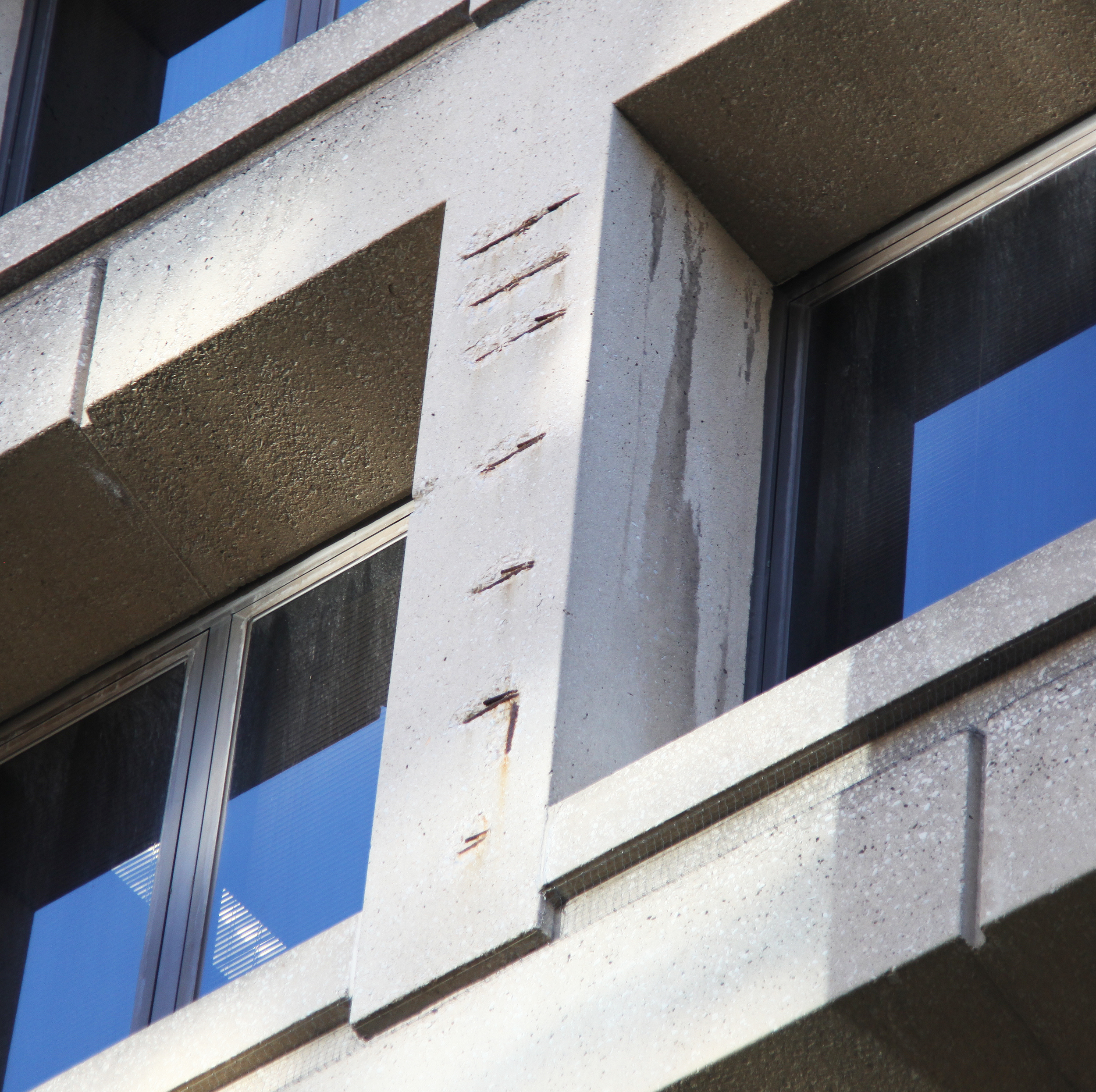
The scope should distinguish visible cracking, areas of missing surface
material, staining, and apparent joint defects from questions requiring another
inspection method. Ask the appointed facade specialist which observations merit
immediate notification, which need closer examination, and which can enter
routine maintenance review. A pilot's responsibility for capturing a photograph
does not by itself assign responsibility for interpreting the building's
condition.
Agree on access and flight feasibility before the capture date. The operator
should define where the aircraft and people can be positioned, the working
distance from the building, and how incomplete coverage will be reported. If a
required surface cannot be captured within those arrangements, price and
schedule an alternative method for that surface rather than marking it complete.
Also settle the destination of the data. An owner using marked-up elevation PDFs
and a spreadsheet needs a different handover from a team integrating findings
into building information modeling (BIM). Request a sample export before
commissioning a large survey.
Capture both context and surface detail
Plan two complementary image sets. Context photographs establish the building,
elevation, and surrounding features. Detailed views show the surface condition
at the scale required for review. They can belong to one coordinated mission,
but a successful model reconstruction does not establish that its texture
contains enough detail to assess a small crack.
A 2024 study in Sensors separated oblique imagery for reconstruction from
photographs facing the facade for defect detection. That distinction helps
explain why an attractive building model and a useful inspection record are
different deliverables. The same study rejected images affected by blur,
reflection, or obstruction before processing. See its
facade capture and defect-mapping methods.
Photogrammetry reconstructs geometry from corresponding features in overlapping
photographs.
PIX4D's acquisition guidance
ties the capture plan to the object, image sampling distance, and overlap;
inadequate acquisition can require another visit. Its general mapping guidance
gives at least 75% forward and 60% side overlap, but those are general starting
values, not a universal specification for every facade.
Have the processing team define overlap in the wall plane and confirm it on a
representative test section. The test should include the actual surface finishes
and difficult features, not just the easiest flat wall. Require context views
connecting detailed strips to their elevation, and additional views where a
projection hides a surface.
Before leaving, inspect original-resolution samples and reconcile captured areas
against the coverage plan. Check whether relevant details are sharp,
distinguishable, and visible without glare or deep shadow. Record a rejected
image's replacement or the resulting coverage gap. Counting photographs alone
cannot show that every required surface is inspectable.
Calculate image scale before promising measurements
Ground sampling distance, or GSD, describes how much surface corresponds to one
image pixel. For a facade, use the camera-to-wall distance and the plane being
photographed. A small nominal GSD is useful for planning, but it is not a
statement of crack-width accuracy.
For a flat wall photographed straight on, the idealized pinhole-camera
relationship is:
Surface sampling distance (mm/pixel) = wall distance (mm) × sensor width (mm) ÷
[actual focal length (mm) × image width (pixels)].
This rearranges
PIX4D's image-scale calculation
for a vertical target. Use actual focal length, not the 35 mm equivalent.
Perspective and departures from a flat, perpendicular target complicate the
scale elsewhere in the image.
For illustration, assume a 13.2 mm-wide sensor, an 8.8 mm lens, a 5,472-pixel
image width, and a wall distance of 5,000 mm. These are hypothetical inputs, not
a recommended camera or flight distance.
Sampling distance = (5,000 × 13.2) ÷ (8.8 × 5,472) = approximately 1.37
mm/pixel.
A hypothetical 3 mm-wide feature would span about 2.2 pixels at that scale. That
arithmetic describes sampling only; it does not prove that the feature can be
reliably identified or measured. Require a demonstration on a known reference
feature under representative conditions before accepting a numerical crack-width
claim.
Keep detail visibility, dimensional measurement, and location
accuracy separate in the specification. The
USGS calibration guidelines
explain that control-point accuracy and tie-point quality affect geometric
accuracy independently of image GSD. A fine pixel size cannot substitute for
geometric verification.
If dimensions matter, ask how scale is established, which reference measurements
independently check the result, where those checks sit on the building, and how
uncertainty is reported. Match that evidence to the quantity being delivered: a
mapped defect location, crack length, or area of missing material need not have
the same error.
Turn photographs into a defect map
A defect map joins an observation to a location the maintenance team can find
again. For a simple building, annotated elevations with floor and bay references
may be sufficient. For complex geometry or an established BIM process, findings
may need coordinates and links to specific building elements.
Use the following handover sequence as a practical specification:
- Retain the originals. Preserve source photographs and capture metadata.
Give each image a stable identifier; keep annotations and crops traceable to
it.
- Establish the reference. Identify the elevation drawing, orthomosaic, or
model version. An orthomosaic combines geometrically corrected photographs
into a common projection; state which facade plane it represents.
- Locate each observation. Assign a finding ID, elevation, floor, bay or
element, source-image ID, and marked region. Include coordinates and units
when the receiving system needs them.
- Review the interpretation. Record the observed feature separately from
its suspected cause. Identify the reviewer and retain uncertain
classifications for follow-up.
- Reconcile duplicates and gaps. One defect visible in several photographs
should retain one finding identity with multiple image references. Obscured
or unusable areas need their own coverage status.
The Sensors study demonstrated projection of image detections onto a BIM
surface. Treat this as an example of integration, not proof that any two
commercial systems exchange findings without preparation. Ask the supplier to
demonstrate one complete export and import using your intended receiving
software.
For repeat surveys, preserve the location convention and finding IDs across
visits. Require new observations to remain distinguishable from changes to
existing findings. A revised model, a different viewing angle, or a different
image scale should trigger a comparability check before a report labels a defect
as having grown. Where a reported change is no larger than the uncertainty in
comparing the two surveys, record it as unresolved rather than confirmed growth.
Set limits on visual, thermal, and automated findings
Visible-light imagery records appearance. It can document an apparent crack,
surface loss, or stain; a photograph alone does not establish the depth, cause,
or remaining capacity of the affected assembly. The Sensors researchers
explicitly limited their work to two-dimensional surface defects and did not
establish their true three-dimensional condition.
Automation also needs review. In that study, deformation joints and shadows
could be mistaken for cracks. Ask how a supplier checks both false alarms and
missed defects on your facade materials. A demonstration containing only
correctly detected examples gives no account of what the system overlooked.
Thermal imagery adds information about surface radiation.
FLIR's thermographic measurement guidance
explains that temperature interpretation depends on emissivity, reflected
radiation, distance, humidity, and atmospheric temperature. Emissivity describes
how effectively a surface emits thermal radiation compared with a reference
blackbody.
If thermal capture is included, require a separate method statement recording
acquisition conditions and the parameters used for interpretation. Label
unexplained patterns as thermal anomalies pending assessment; do not turn a
colored region into a confirmed moisture or delamination diagnosis without
supporting investigation. Agree on what follow-up will resolve each suspected
condition.
The guide to
what drone-inspection evidence can prove
explains the wider distinction between observation, measurement, and diagnosis.
For this project, put those distinctions directly into the deliverables and name
who can authorize the next action.
Specify measurable deliverables
Ask for files and checks that another professional can examine. The following is
an editorial procurement checklist informed by the acquisition, calibration, and
mapping sources above; it is not a prescribed inspection standard.
Scroll horizontally to compare all columns.
Make coverage measurable without hiding exclusions. One useful contract metric
is usable inspected area divided by total agreed inspection area, with numerator
and denominator stated in square metres. If a hypothetical 1,000 m² scope
contains 900 m² of usable coverage and 100 m² obscured by access constraints,
report 90% usable coverage plus the 100 m² gap. Do not silently redefine the
scope as 900 m² and call it complete.
Area coverage alone is insufficient when a small omitted feature is critical.
Maintain a separate list of required elements and their status. Keep findings
awaiting review separate from areas where review found no reportable defect.
Assign responsibility and timing for revisits, closer inspection, and
interpretation of urgent observations before accepting the final report.
Questions to settle before awarding the work
- What is the smallest feature the proposed capture can demonstrate on this
facade, and what evidence supports that claim?
- Which surfaces will remain unseen, and who will inspect them by another
method?
- Can the supplier trace a finding from an editable register through the
original photograph to its building location?
- Which quantities will be measured, with what checking method and reported
uncertainty?
- Who reviews automated detections, assesses the condition, and communicates
urgent findings?
- What happens to incomplete coverage, unusable photographs, and unresolved
classifications?
- Will the owner retain usable images and finding data after hosted access ends?
Commission a representative capture-and-handover sample before scaling the work.
Accept the method when the facade specialist can see the required detail,
relocate findings, understand the measurement limits, and use the exported
records. That gives the full survey a concrete purpose: a maintenance team that
knows where to investigate next and why.
Source notes
Last checked: September 6, 2026.