On This Page
Define the deliverable before the flight
Start with a short scope agreed by the person who will use the data. A
construction manager tracking visible progress and an engineer importing
elevations into a design model need different deliverables, even when the flight
boundary is identical.
Record the area of interest as a supplied boundary, the collection date or
repeat interval, the surfaces and features that matter, and any areas that may
be excluded. Name the receiving application and version. Request a sample import
early enough to change the export specification before fieldwork.
A deliverable schedule to agree with the client
Scroll horizontally to compare all columns.
This is an editorial specification template, informed by
PIX4Dmapper's documented outputs
and
USGS mapping workflows,
checked September 7, 2026. It does not prescribe a universal file package or
certify any result.
Keep resolution and accuracy as separate requirements. Ground sampling
distance, or GSD, describes the ground distance represented by a pixel. It does
not establish how closely a mapped feature matches its independently measured
position. USGS explicitly warns against assigning higher positional accuracy
simply because the imagery has smaller pixels in its
UAS calibration guidelines.
Ask the client to state horizontal and vertical accuracy requirements
separately, with units, the reporting statistic, the applicable standard and
version where required, and the method of independent checking. An unexplained
request for “survey-grade” data leaves too much unresolved to price or plan
reliably.
Set the control and coordinate plan
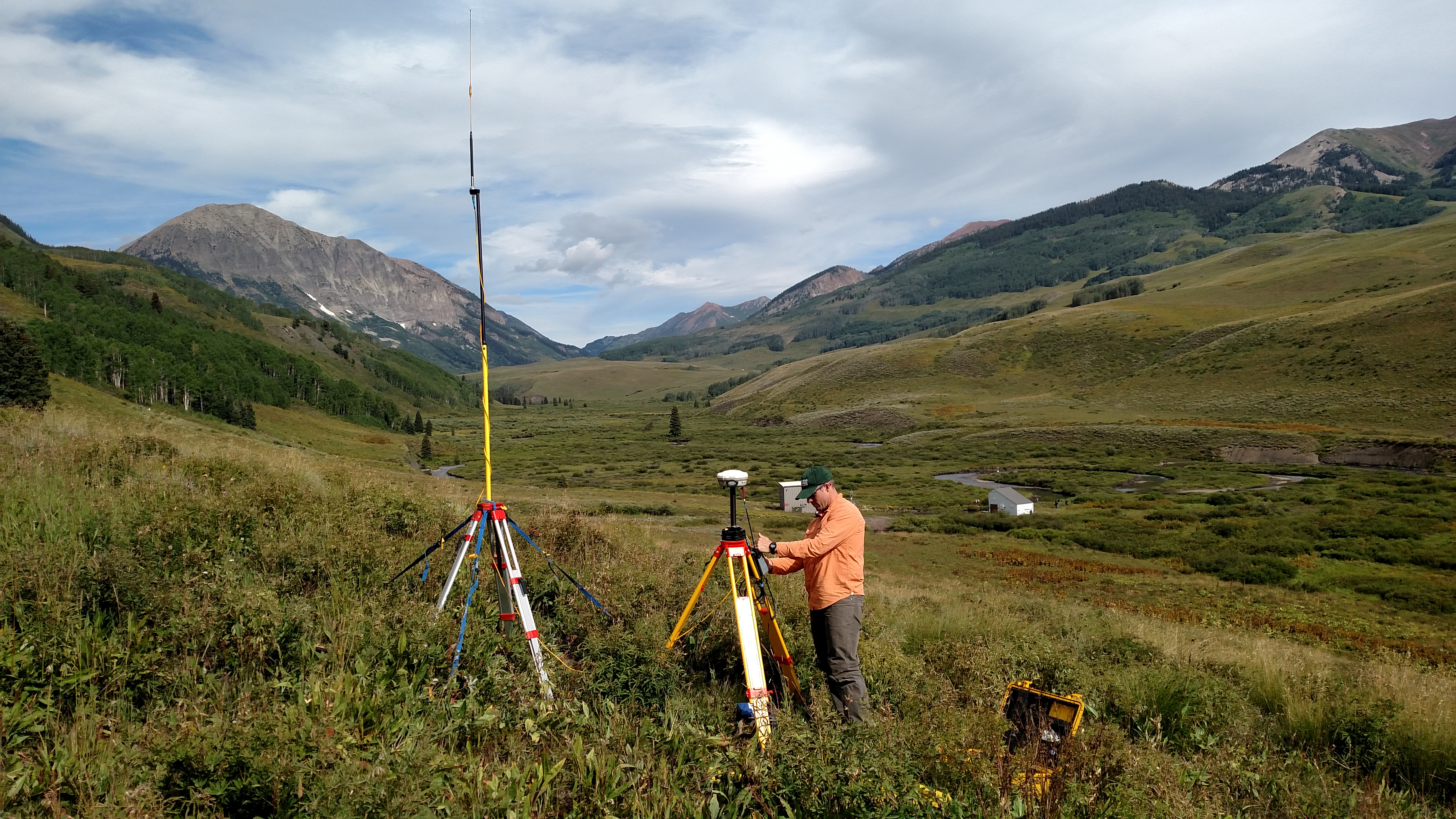
Define the horizontal coordinate reference, vertical datum or height reference,
units, and any project-specific transformation with the receiving team. Record
the reference frame and epoch where relevant. A coordinate-system label alone
may not explain how heights should align with the client's existing data.
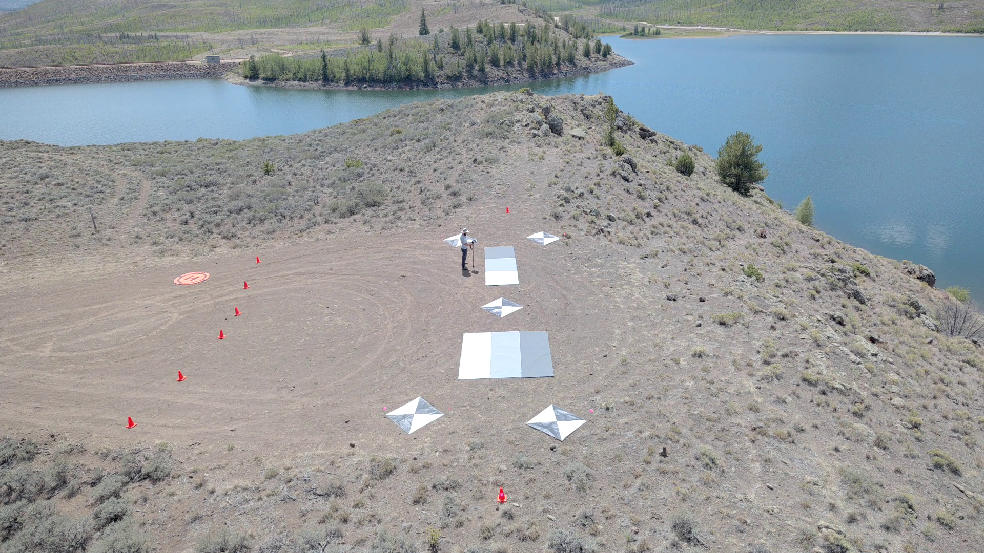
Ground control points are measured locations used to constrain the
reconstruction. Checkpoints provide locations against which the result can
be evaluated independently; reserve their measured coordinates from the
adjustment used to fit the model. Place and measure both under the project's
control plan, with useful coverage across the site and its elevation range. USGS
treats control quality, spatial distribution, camera calibration, and flight
design as interdependent.
RTK or PPK image positioning can improve georeferencing, but the positioning
feature on the aircraft is not a delivered-map test.
PIX4D's accuracy guidance
distinguishes relative accuracy within a model from absolute accuracy in a
reference frame and recommends checkpoints to assess the latter.
Real-time kinematic positioning (RTK) and post-processed kinematic positioning (PPK)
differ in when corrections are applied: during collection or afterward from
recorded observations. Assign responsibility for the control survey, target
placement and recovery, correction data, and final accuracy report. If a
correction connection fails, establish whether the configured system records
what is needed for post-processing. Ask the provider to demonstrate the recovery
workflow for the actual aircraft, camera, correction source, and software.
When the intended decision reaches beyond documenting visible conditions, our
explanation of
what drone imagery can establish
helps distinguish a useful visual record from stronger measurement evidence.
Turn resolution into a capture plan
Choose the camera and working distance together.
PIX4D's GSD guidance
identifies flight height above the target, sensor width, focal length, and image
width as the relevant inputs. Terrain and camera angle can change GSD across a
mission.
For a downward-looking camera above approximately level terrain, a useful
planning approximation is:
GSD in metres per pixel = height above the target in metres × sensor width in
millimetres ÷ (focal length in millimetres × image width in pixels).
Use actual focal length, not a 35 mm equivalent. The result is a sampling
estimate, not an accuracy prediction. Verify camera calibration, focus, exposure
and motion blur for the intended conditions.
Worked capture-spacing example
Assume a hypothetical project has a planned GSD of 0.02 m/pixel and captures
6,000 × 4,000 pixel images. With the long image dimension across the flight
track, each image covers approximately 120 m across track and 80 m along track
on level ground.
If the planner selects 80% forward overlap and 70% side overlap for this
example:
- Along-track spacing = 80 m × (1 − 0.80) = 16 m between exposures.
- Line spacing = 120 m × (1 − 0.70) = 36 m between flight lines.
- At a constant ground speed of 5 m/s, exposure interval = 16 m ÷ 5 m/s = 3.2
seconds.
These are calculated planning values, not a tested camera configuration or
universal settings. The example assumes a downward-looking camera, level ground,
steady orientation and speed, and no missed exposures. Confirm that the camera
can sustain the trigger interval with the selected image format and storage
card. A different image orientation changes the spacing calculation.
As a provider-specific starting point,
PIX4Dmapper recommends
at least 75% forward and 60% side overlap for its general case. It recommends
higher overlap for some surfaces, including fields and dense vegetation. Apply
the guidance appropriate to the actual scene and processing workflow rather than
treating one pair of percentages as a guarantee.
Review the route against terrain, obstacles and the required edges of the final
map. Include collection beyond the output boundary where permitted so the
boundary is supported by overlapping views. A constant altitude relative to
takeoff does not maintain constant distance above sloping ground. If terrain
following is used, check the elevation model and obstacle treatment; a terrain
surface is not an obstacle survey.
For a flat site orthomosaic, a downward-looking grid may fit the job. If
vertical faces are deliverables, plan views that can actually see them. More
photographs of the roof will not supply a hidden facade. Avoid promising ground
elevations beneath continuous cover merely because software can export an
elevation surface.
Build the field schedule around constraints
Keep the technical collection plan and the operating permissions aligned. For a
U.S. mission conducted under Part 107, confirm the pilot, registration and
Remote ID requirements, applicable airspace authorization, and whether any
proposed operation needs a waiver. The
FAA commercial-operator guidance
is the starting point; map software accepting a route does not authorize the
flight.
Before assigning a collection window, resolve site access, launch and landing
areas, people and vehicle movements, visibility of the aircraft, obstacles,
weather limits, and the response to lost communications. Use the aircraft's
documented limitations and the operator's procedures to set go/no-go and return
decisions.
Budget the whole visit: travel within the site, control measurement, target
deployment, briefings, takeoff and transit, turns, battery changes, landing
reserve, data copies, and a possible repeat flight. Do not turn an advertised
endurance figure directly into an acreage promise. Separate flying time from
crew time and processing time in the proposal.
For multiple sorties, plan overlapping coverage between them and consider
changes in illumination, weather and the scene. PIX4D advises similar conditions
across flights used in one project. On an active construction site, coordinate
collection with the person controlling site activity so a changing stockpile or
moving equipment does not undermine the intended snapshot.
Check the data before leaving
Make the person responsible for processing part of the departure decision. While
the crew can still recollect data, inspect actual images for sharpness,
exposure, target visibility and missing coverage. Confirm the image sequence,
geotags and required positioning records, then make verified copies before cards
are cleared or reused.
Where practical, run an initial alignment or preview reconstruction in the
field. It can expose disconnected image groups or obvious gaps. It cannot
substitute for final accuracy evaluation. USGS's calibration guidance connects
acquisition and quality control, while PIX4D's output documentation describes
quality reports at successive processing stages.
At final processing, review image alignment and camera calibration before
building the dense reconstruction and exporting surfaces or maps. Preserve the
software version, settings, control inputs and excluded images. Report
checkpoint errors against the agreed criteria, including the number and
distribution of points and any areas they do not adequately represent.
Investigate failures before declaring the delivery complete; a small fitting
error at control points is not an independent validation result.
Open the exported files in the receiving application and check their location,
units, height reference, coverage and accompanying files. Review edges,
reflective surfaces, vegetation and other weakly reconstructed areas. PIX4D
notes that local accuracy can vary with scene content even within a successfully
reconstructed model.
Deliver the usable outputs with the coordinate definition, capture date,
processing and accuracy reports, coverage exclusions, and an agreed record of
retained raw data. For repeat monitoring, document changes in collection or
processing so the next team can distinguish a site change from a workflow
change.
Ask these questions before accepting a proposal
A provider should be able to answer the following in terms of your project:
- Which files and measurements are included, and have you confirmed an import
into our application?
- What resolution is planned, what positional accuracy will be evaluated, and
how are those requirements kept separate?
- Who supplies control and independent checks, and how will coordinates and
heights align with our existing data?
- Which surfaces or areas may be missing, obscured or unsuitable for
measurement?
- What happens if weather, missing images, correction failure or processing
quality requires another visit?
- Does the price include control work, processing, quality reporting,
revisions, file delivery and raw-data retention?
Before mobilization, have the client, pilot and processing lead review the same
scope, flight boundary and delivery specification. Resolve any requirement the
proposed collection cannot demonstrate, then revise the mission or deliverable
before committing field time. The job is complete when the data can be used and
checked for its agreed purpose.
Source notes
Last checked: September 7, 2026.