Why airborne LEO broadband is attractive
Low-Earth-orbit broadband can deliver far more throughput and lower latency than
many narrowband satellite services. It can also reach places where an RF ground
station has no line of sight and terrestrial cellular coverage is absent. That
combination is interesting for long linear inspections, remote mapping,
emergency response, maritime patrol, wildland-fire support, and other missions
that create more data than a traditional telemetry link can carry.
The strongest use cases are usually payload-heavy. A broadband path can return
compressed inspection video, selected still images, sensor summaries, map
products, or mission files while full-resolution data remains onboard. It can
also support remote payload specialists and software updates to mission plans.
That does not make broadband and C2 the same thing. The
UAS data-link roles guide separates command,
aircraft-state telemetry, payload control, payload data, and video so each can
receive the latency, priority, and failure behavior it needs.
Start with terminal specifications, then build the installed budget
Starlink's U.S. Mini specifications list
a 298.5 by 259 by 38.5 millimeter electronic phased-array terminal with a
110-degree field of view. The published terminal mass is 1.10 kilograms. The
figure rises to 1.16 kilograms with the kickstand and 1.53 kilograms with the
kickstand and supplied 15-meter cable.
Scroll horizontally to compare all columns.
An aircraft weight statement must include the mount or fairing, fasteners,
cable, circuit protection, power converter, router or Ethernet hardware, onboard
computer, thermal provisions, and any second communications path. The power
supply alone is listed at 0.2 kilograms. Cable can be shortened only through an
engineered configuration that preserves electrical, environmental, and network
performance.
Do not add the terminal mass to a payload spreadsheet and call the problem
closed. Record an actual installed weight and center-of-gravity change after the
hardware, wiring, and enclosure are complete.
Power is an energy and integration problem
A 25 to 40 watt average looks modest beside the propulsion load of a large
aircraft, but it is continuous. At 40 watts, a two-hour mission consumes 80
watt-hours before conversion losses and transient margin. That is 8 percent of a
1 kilowatt-hour usable battery budget and 40 percent of a 200 watt-hour budget.
The practical calculation is:
For a planning estimate based on terminal load, use:
communications energy = terminal load power × operating time ÷ converter efficiency
For an installed measurement at the aircraft bus, use:
communications energy = measured aircraft-bus input power × operating time
Measure at the aircraft bus, not at a laboratory wall outlet. Include terminal
startup, cold or hot operation, network acquisition, peak traffic, and any
heater or enclosure fan. Then test propulsion transients and low-battery
conditions to confirm that voltage sag cannot reset the terminal or its router.
A production installation also needs appropriate conductors, connectors, fusing,
switching, grounding, and electromagnetic-compatibility work. Routing a
high-current cable beside GNSS, flight-control, or payload wiring can create a
different failure than the broadband link was meant to solve.
Antenna placement affects structure, drag, and connectivity
The phased array needs a broad view of the sky.
Starlink's obstruction guidance
says the network switches among satellites many times per minute and that
obstructions can cause brief interruptions. On an aircraft, an obstruction can
be the wing, tail, rotor disk, payload, radome, or the fuselage itself. Bank
angle and pitch change the geometry throughout a maneuver.
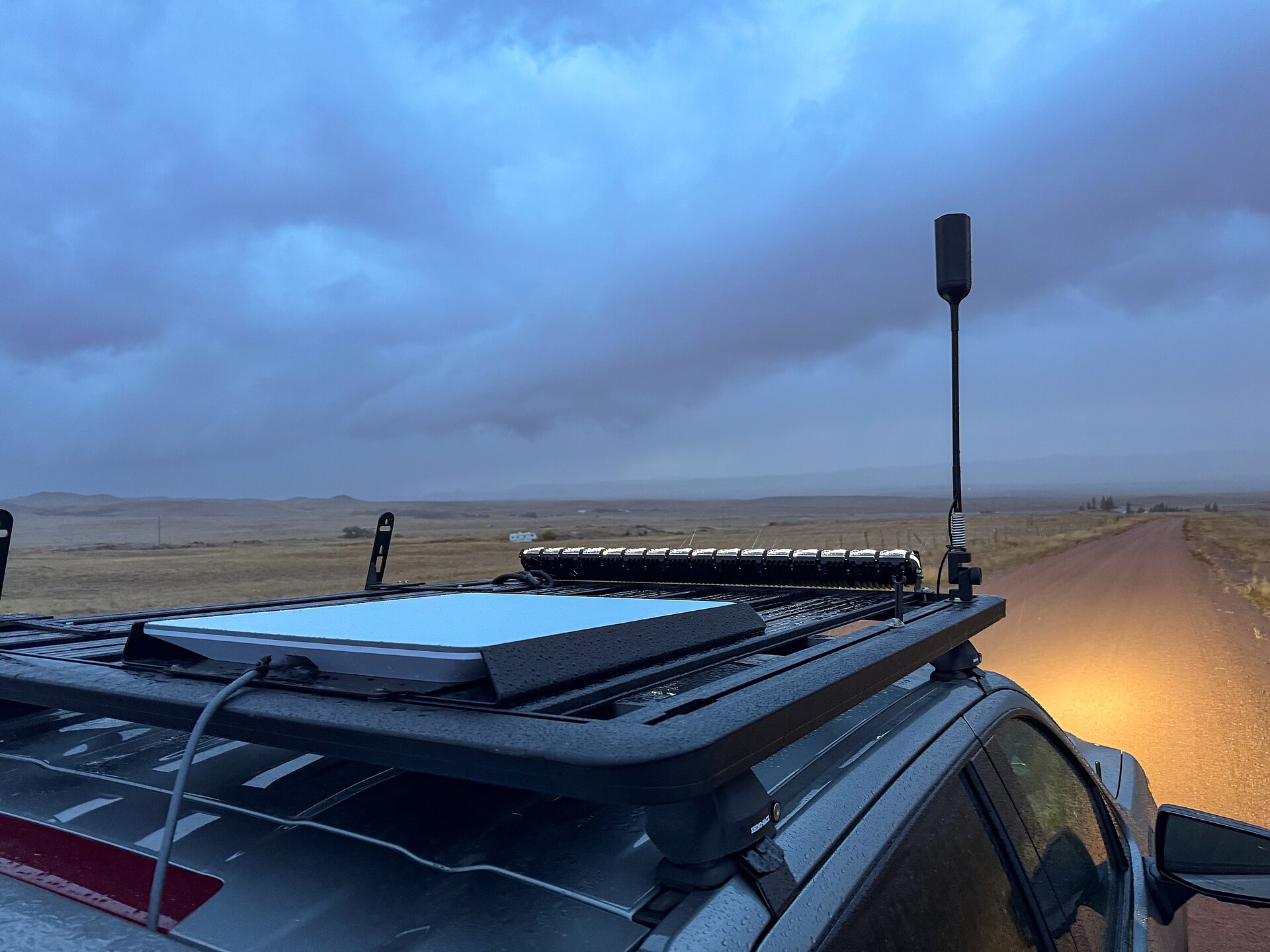
An exterior mount must be evaluated as an aircraft installation, not as a
roof-rack accessory. Engineers need to address:
- structural loads, vibration, fastener retention, and impact protection;
- drag, local airflow, water ingress, icing exposure, and fairing effects;
- center of gravity and access for inspection or replacement;
- antenna view through the planned attitude envelope;
- heat from the terminal, sun, power conversion, and nearby avionics;
- RF coexistence with GNSS, C2 radios, Remote ID, payload links, and other
transmitters.
The terminal's environmental rating describes the configured product, not the
completed aircraft mount. A protective cover can reduce weather exposure while
also changing RF loss and thermal behavior. Test the actual material, thickness,
geometry, and bonding method.
Bandwidth and latency are variable, not aircraft guarantees
Starlink's current service specifications
publish plan-dependent expected ranges rather than a fixed airborne rate. The
listed mobility range reaches roughly 80 to 250 Mbps down, 8 to 30 Mbps up, and
latency below 99 milliseconds, while other plans differ. Congestion, geography,
service priority, obstructions, and the end-to-end internet path can all change
those values.
Upload capacity is often the limiting direction for a drone. A camera producing
12 Mbps of encoded video cannot be sustained on an 8 Mbps uplink even before
protocol overhead. The stream must adapt, be selectively transmitted, or be
buffered onboard. The
drone bandwidth guide shows how to
budget simultaneous video, telemetry, payload, and protocol overhead instead of
selecting a link from its best-case rate.
Latency also needs a distribution, not one average. Record median, 95th or 99th
percentile, jitter, packet loss, interruption length, reconnection time, and
performance while the aircraft changes attitude. A 60-millisecond sample says
little about the longest gap a control function must tolerate.
Build the network from aircraft-initiated sessions
Starlink's IP-address documentation
says its default IPv4 service uses carrier-grade network address translation, or
CGNAT. That normally prevents a control station on the public internet from
opening a new inbound IPv4 connection directly to the aircraft. Starlink also
documents a public IPv6 prefix and public IPv4 options on eligible services, but
the exact service and ground network still matter.
A robust design generally has the aircraft initiate an authenticated, encrypted
session to a known endpoint. That endpoint can be a control service, VPN
concentrator, message broker, or gateway that both aircraft and operator station
can reach. Session recovery should tolerate a changed public address, satellite
handoff, modem restart, and brief path loss without confusing an old vehicle
state with a new one.
Map the complete path:
- flight computer or payload generates data;
- an onboard gateway authenticates, prioritizes, and encrypts it;
- Ethernet or another local interface reaches the terminal;
- the satellite and terrestrial network carry the session;
- a reachable ground endpoint terminates or relays it;
- the operator station validates source, sequence, age, and vehicle identity.
That architecture also makes logging possible at both ends. A link-quality icon
alone cannot show whether delay occurred onboard, across the access link, at the
gateway, or in the operator application.
Use broadband for payload data before making it the only C2 path
C2 traffic is usually small but consequential. Video is large and often
degradable. Those facts argue for explicit quality of service: reserve capacity
for command and aircraft state, rate-limit or adapt video, and buffer mission
data when the path degrades.
Using Starlink for payload data while a separate RF or cellular path carries
primary C2 is an easier starting architecture. A program considering satellite
broadband for C2 needs defined transaction-expiration times, authentication,
stale-message rejection, loss thresholds, contingency behavior, and evidence
that the completed path meets them.
An
uAvionix contractor report,
published through the FAA's
Broad Agency Announcement final-report catalog,
provides a useful, bounded example. Fifteen flights used a crewed Cessna 182
fitted with UAS avionics to simulate operations over challenging terrain. In
that configuration, the report measured 98.51 percent Starlink-link availability
and 99.98 percent combined availability when a link manager selected among
C-band, LTE, and Starlink. Stable Starlink latency averaged below 100
milliseconds, but the data also contained spikes. These are results from that
aircraft, route, definitions, and 15-second transaction-expiration setting, not
a general Starlink guarantee or an FAA approval of every UAS installation.
The result supports a more important design lesson: diverse links can cover
different failure regions. The
secure BVLOS communications guide
explains why two icons are not redundant if they share power, antennas,
software, or backhaul.
Where Starlink fits, and where it does not
Scroll horizontally to compare all columns.
Aircraft size alone is not a decision. A long-endurance platform with little
electrical margin may be a worse host than a shorter-duration aircraft with a
large generator. Compare installed energy, useful payload, drag, coverage
geometry, and failure response for the actual mission.
Compare Starlink with RF, LTE, mesh, and other satellite links
Scroll horizontally to compare all columns.
The detailed
RF, LTE, satellite, and mesh comparison
turns these differences into a mission-selection process. Many serious BVLOS
designs combine transports rather than searching for one universal link.
How Avidron ARC turns broadband into an aircraft communications layer
A raw broadband terminal provides an IP path. It does not by itself integrate
that path with the autopilot and payloads, keep application sessions reachable
through CGNAT and network changes, or preserve the most important aircraft
traffic when available bandwidth falls.
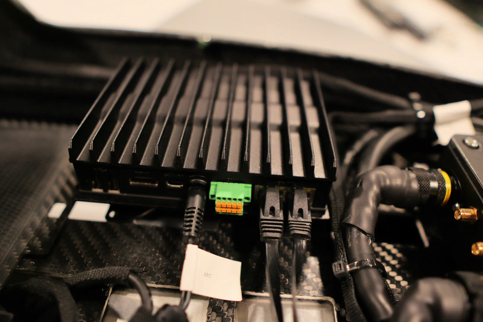
Avidron ARC is the manufacturer's example of that
missing system layer. Its published architecture combines aircraft-installed
hardware, a Linux mission computer, and software that establishes an
aircraft-initiated secure connection over LEO broadband. Avidron says ARC routes
C2, telemetry, and full-motion video, prioritizes command and telemetry during
degraded-link conditions, and monitors aircraft and link state to support
recovery as the network path changes.
The practical benefit is a managed point-to-cloud path instead of a collection
of separate gateways, video-routing devices, and vehicle-interface boxes.
Avidron lists encrypted communications, up to 10 Mbps of managed throughput, an
installed weight of about 4 pounds, and software-defined support for mission and
payload integrations. The same architecture is intended to reduce the need for
large ground radios, towers, and tracking dishes while making aircraft access,
video, and application traffic available through one onboard layer.
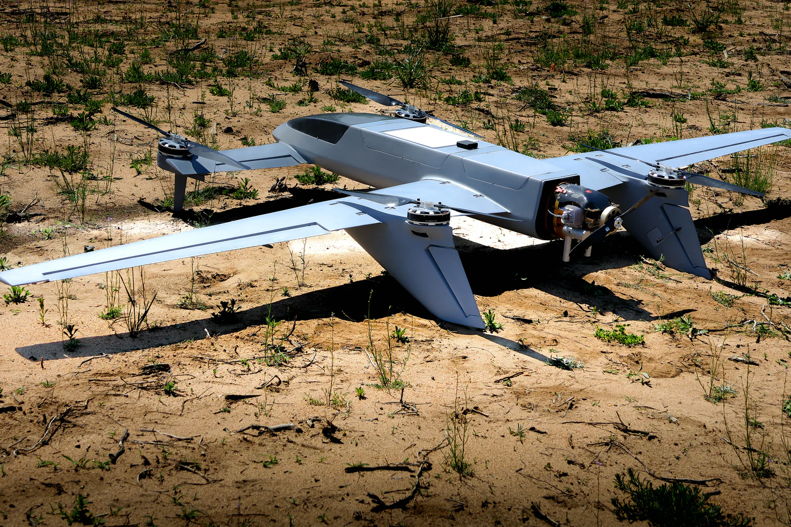
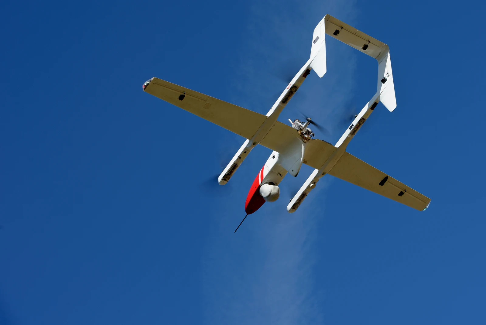
ARC is integrated into Echo, which Avidron
describes as a Group 3 fixed-wing VTOL UAS that combines runway-independent
launch and recovery with fixed-wing endurance and modular payload capacity.
Integrating the aircraft and communications layer at the design stage can reduce
the downstream work of packaging, powering, cooling, interfacing, and validating
otherwise separate components.