On This Page
Confirm which elevation you are comparing
Identify the file and the measured quantity first. A point-cloud Z value, a
terrain raster's pixel value, a camera's geotag altitude and a flight display's
height above takeoff are different quantities. Record the exact field and its
documented reference instead of treating every value labeled “altitude” as a
surveyed ground elevation.
Also check that the two measurements represent the same surface. A digital
surface model (DSM) can follow roofs and vegetation; a digital terrain model
(DTM) aims to remove above-ground objects. An orthomosaic is an image map, not
itself a grid of terrain elevations. PIX4D's
output definitions
explain these differences. Choose the surface deliverable before interpreting
its elevations.
For diagnosis, compare clearly identifiable, stable locations on the surface the
contract actually requires. A rooftop compared with a ground benchmark can
produce a real height difference that no datum conversion should remove.
Separate the height reference from the map projection
The horizontal coordinate reference system explains where a point lies across
the map. The vertical reference explains what its elevation is measured from.
Selecting the right projected grid does not, by itself, establish the meaning of
the Z coordinate.
Three terms resolve much of the confusion:
- Ellipsoidal height, h: height relative to the mathematical ellipsoid used
by the reference frame.
- Orthometric height, H: height referenced to the geoid, the gravity-related
reference surface associated with this height system.
- Geoid height, N: the separation between that geoid and ellipsoid, with a
sign that matters.
The practical relationship is H = h − N. NOAA's
technical explanation of GPS and orthometric heights
gives the equivalent h = H + N. A negative N means subtracting a negative
number: the orthometric height is greater than the ellipsoidal height. Do not
choose the sign merely because the map looks high or low.
A geoid model must match the reference-frame pair. NOAA describes GEOID18 in
terms of NAD83(2011), epoch 2010.0 ellipsoidal heights and NAVD88 orthometric
heights. That is a specific relationship, not a generic conversion from anything
called WGS84 or “GPS altitude.” Confirm the input frame, realization and epoch
where relevant, the required vertical datum, the model and its geographic
coverage. See
GEOID18 technical details.
Check these definitions separately for image positions, ground control,
checkpoints and exports. A receiver may already have converted its reported
elevations. Applying another geoid correction to those values can introduce an
error instead of removing one. Identify the input-height setting as well as the
selected output datum.
Use the residual pattern to choose the next check
For each surveyed checkpoint, calculate a signed vertical residual using
comparable coordinates and units:
Vertical residual = delivered surface elevation − surveyed checkpoint elevation.
Plot or tabulate residuals by location and elevation. The patterns below are
diagnostic leads synthesized from the cited height, unit, base-position and
reconstruction guidance; none identifies a cause by itself.
Scroll horizontally to compare all columns.
For unit checks, one international foot equals exactly 0.3048 meter; a U.S.
survey foot equals 1200/3937 meters. The
NIST explanation
identifies their approximately two-parts-per-million difference. Neither is
interchangeable with a meter.
For scale, 100 meters is about 328.084 international feet. The difference
between the two foot definitions at a numeric value of 100 feet is only about
0.061 millimeter. That small difference cannot explain a 28-meter height
discrepancy at that value. Larger coordinate magnitudes can make a
foot-definition mismatch more consequential. Preserve the actual units of legacy
data rather than changing its label to the preferred modern unit.
Audit base coordinates and antenna height
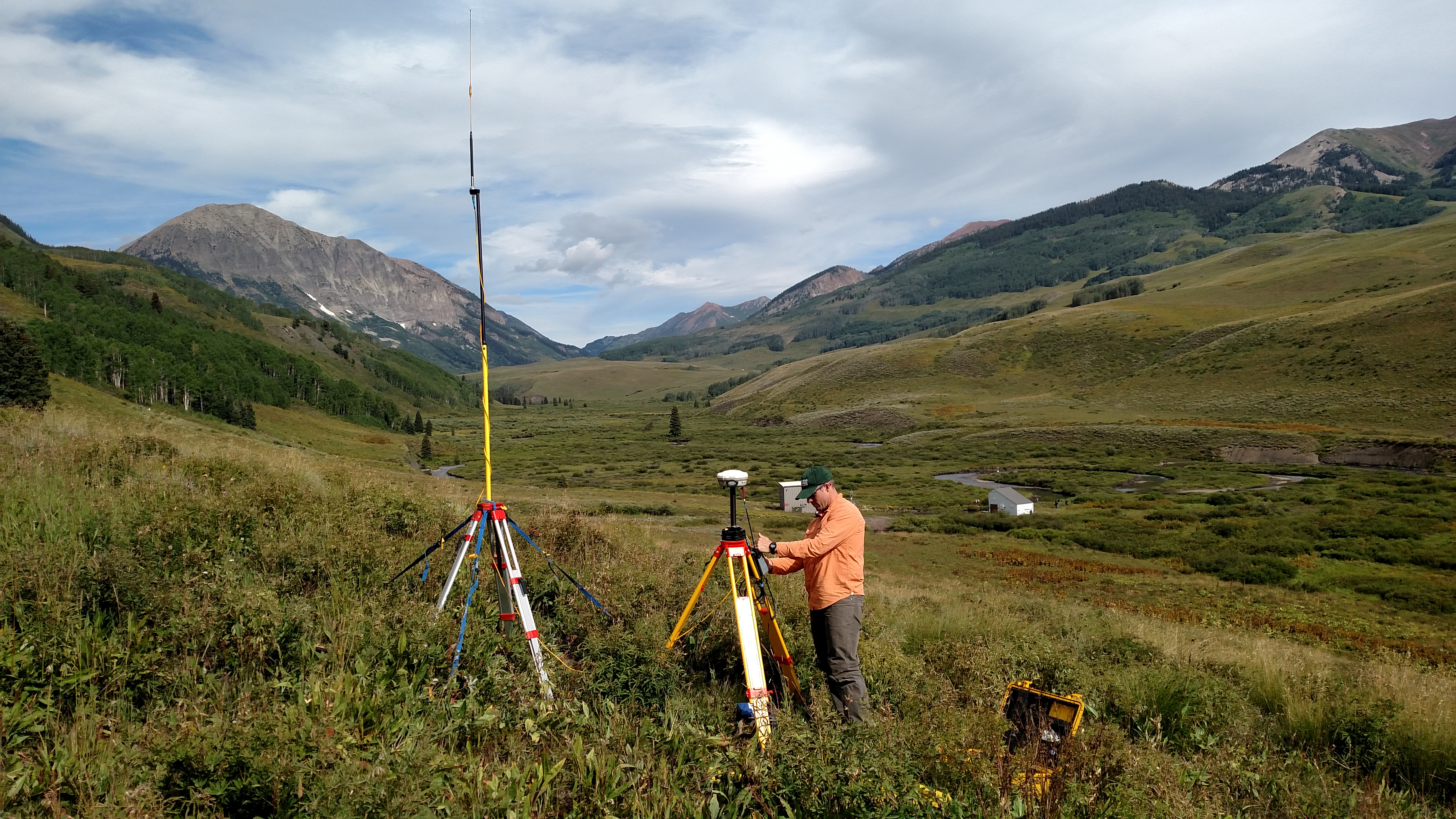
Real-time kinematic (RTK) positioning uses a base or reference network to help
determine the rover's position. A precise relative solution still depends on the
base's absolute coordinates. Emlid's
base-placement guidance
illustrates how an incorrectly positioned base shifts rover coordinates. A fixed
RTK status does not certify that the entered base elevation belongs to the
client's datum.
Retrieve the base record: coordinate source, reference frame, height type and
occupied mark. Distinguish a surveyed position from a temporary averaged
position.
Then follow the receiver's height-entry convention. The ground mark, antenna
reference point and antenna phase center are different locations. Software may
already account for part of that geometry. Emlid documents an automatic antenna
offset for its Reach RS/RS+ workflow; that is a reason to inspect the exact
receiver instructions, not to transfer its offset to another model. Check the
measured pole or tripod height, measurement method, units and any correction
already applied.
If the base record is wrong, preserve the observations and regenerate affected
outputs through a supported workflow. Check that all deliveries use the
corrected solution. Keep the roles of surveyed control and independent checks
explicit.
Worked example: a map about 28 meters too low
This is an illustrative calculation, not a flight test or surveyed site. Assume
the project requires orthometric heights in meters, but the export retains
ellipsoidal heights. The correct frame-compatible geoid model independently
supplies N = −28.000 m across this small example area; its variation is assumed
negligible for the calculation.
Three checkpoints were held out of georeferencing. They give the following
hypothetical comparisons:
Scroll horizontally to compare all columns.
The raw mean residual is −27.9867 m, rounded to four decimals. That suggests a
shared offset. It does not establish that the offset is a geoid correction: the
base and height metadata must independently support that diagnosis.
At A, H = 72.020 − (−28.000) = 100.020 m. Applying the documented conversion
leaves residuals of +0.020, −0.010 and +0.030 m. Their mean is +0.0133 m and
their vertical root mean square error is:
RMSEz = √[(0.020² + (−0.010)² + 0.030²) / 3] = 0.0216 m, approximately 2.16 cm.
These three values illustrate arithmetic only. They do not establish compliance
with a survey standard, the quality of the reference measurements, or accuracy
across an entire project.
Two distinctions control whether this correction is acceptable. First, the
−28.000 m model value was established independently. If you instead choose an
offset by averaging these residuals, the same points become part of the
adjustment; reserve other independently surveyed points to test the result.
Second, a constant shift is only an approximation where geoid separation varies.
PIX4D's
geoid-output guidance
warns that it can introduce inaccuracies over larger areas or where that
separation changes significantly.
A metadata correction says what existing numbers already mean. A coordinate
transformation computes different numbers in another reference system. Confusing
the two can make a file display plausibly while preserving the wrong elevations.
If a file contains correct orthometric heights but lacks their reference
information, correct the metadata from documented provenance. Esri's
Define Projection documentation
explicitly says that the operation does not change geometry. Assigning an
orthometric reference to numbers that are actually ellipsoidal heights does not
convert them.
For a real transformation, specify the actual source and destination systems,
units, operation and required model files. Esri's
Project documentation
describes a separate vertical-transformation option and its prerequisites. A
horizontal reprojection alone need not alter Z values. That tool's
feature-geometry workflow is not a recipe for changing elevation-raster pixels;
use a documented operation for the actual delivery format.
Trace one recognizable location through input, processed model, export and
receiving software. Record both the numeric elevation and its reference at each
stage. This reveals where the discrepancy first appears and whether a conversion
was skipped, applied twice, or merely relabeled.
Verify the corrected delivery
Check the files the client will use, after import into the receiving
application. Preserve checkpoint locations, survey provenance, units, residual
sign convention, sampling method and before/after results. Include enough
spatial and elevation coverage for the project's specification; three
illustrative points are not a recommended survey design.
PIX4Dmatic distinguishes
checkpoints from points used for georeferencing.
Independence also requires scrutiny of the reference survey: measurements tied
to the same incorrectly entered base cannot expose that common error. Use
reference control whose datum and uncertainty are established independently of
the suspected fault.
Review the residual pattern as well as the summary statistic. If
location-dependent errors remain, investigate them before applying another
blanket offset. Keep original files, processing settings and correction history
so the revised point cloud, terrain model and derived products can be traced to
the same solution.
Document the horizontal reference, vertical datum, geoid model, units and
transformation with the delivery. The
USGS Lidar Base Specification's processing requirements
illustrate explicit reference-system documentation; its program rules do not
automatically govern every commercial drone contract. Agree the applicable
accuracy measures and reference quality with the receiving team.
Accept the correction when its cause is documented and independent checks of the
final delivery meet the agreed requirement. If the cause remains uncertain,
retain the original data and resolve the reference chain before using the
elevations for design, quantities or repeat-survey comparisons.
Source notes
Last checked: September 9, 2026.