On This Page
What the sensors can establish
A visible-light camera records the surface facing it. Concrete spalls, exposed
reinforcement, staining, and coating deterioration can be useful inspection
targets. Fatigue cracks in steel are harder: dirt, corrosion, viewing angle,
vibration, and poor illumination can obscure or imitate them. The 2024 National
Academies report documents these limitations in its
review of bridge-inspection research.
The practical distinction is between recording an indication and establishing
its engineering significance. A photograph of corrosion does not, by itself,
measure remaining steel thickness. Specify the follow-up needed to resolve the
question, whether that means closer access, cleaning, contact measurement, or
another inspection technique.
Thermal cameras record temperature patterns. Under suitable conditions, those
patterns can help locate possible concrete delamination, where layers have
separated. They can also mislead. FHWA's
2021 effective-practices report
describes thermal effects from underlying stringers and deck obstructions, and
calls for sounding or other techniques to confirm delamination extent. A colored
thermal patch therefore needs interpretation and confirmation before it becomes
a repair quantity.
Photogrammetry matches features across overlapping photographs to reconstruct
geometry. The resulting model can organize observations spatially, but a smooth
surface in the model is not proof that the original surface was completely
observed. Keep the photographs available alongside the reconstruction. Our guide
to
what drone-inspection evidence can prove
explains the broader distinction between observation, measurement, and
diagnosis.
Why the underside changes the mission
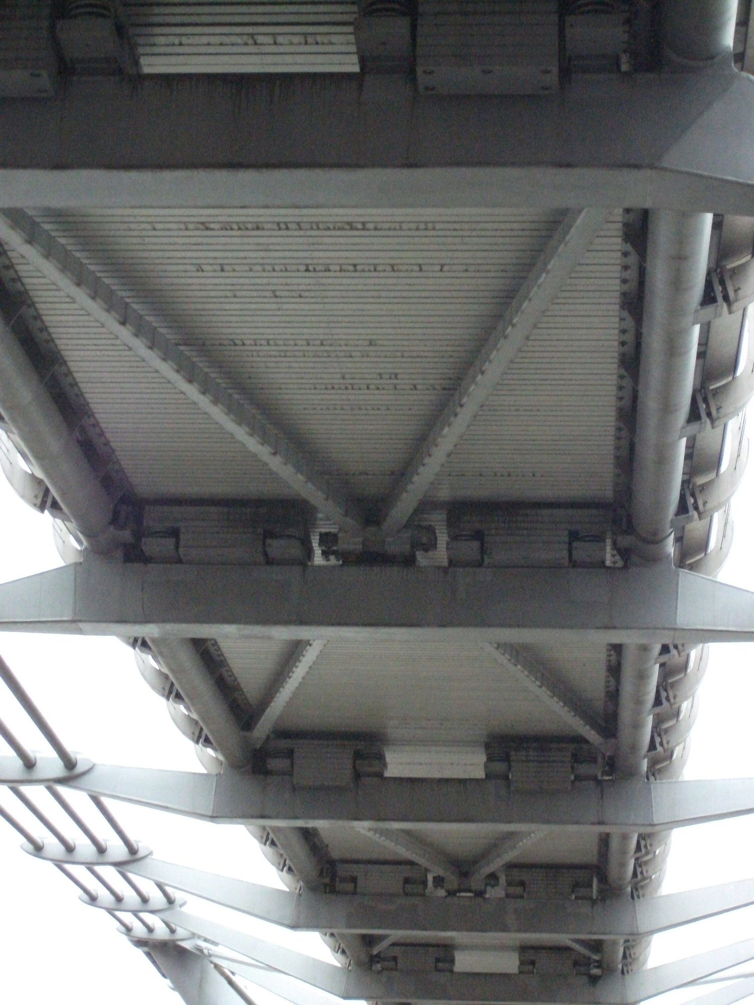
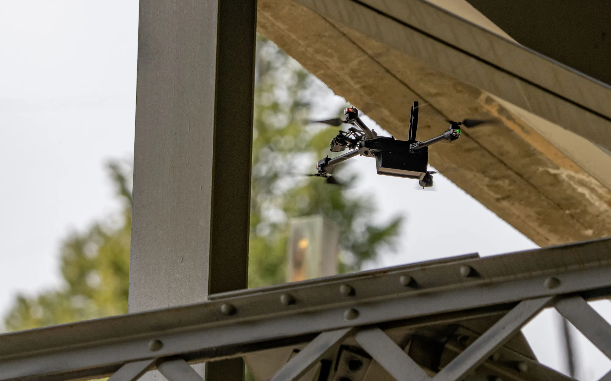
Open-air flight beside a bridge and flight between its girders are different
operating problems. The deck can obstruct satellite navigation, while steel,
restricted clearance, and poor camera angles complicate access. Looking inward
with a zoom camera from outside may leave interior surfaces hidden. These are
documented limitations in the
National Academies research review.
The report's own
field findings make
the tradeoff concrete. The smaller of two aircraft configurations reached more
areas but was less stable; the larger system's zoom lens supported more distant
imaging. In one closely spaced girder bay, proximity-sensor behavior caused
uncomfortable drift. Flights below girder flanges could view much of the
structure while leaving the upper face of the bottom flange unseen. Those
findings concern the tested systems and structures, not every current aircraft.
Use that evidence to ask for a demonstration on representative geometry. An
upward-looking camera helps only if the complete aircraft can reach a useful
viewpoint, hold it, and leave safely. Require the proposed crew to identify
inaccessible bearing faces, connections, and girder surfaces before promising
complete coverage.
The flight plan should also address loss of navigation or communications under
the deck. Ask what the particular aircraft will do and whether its recovery
behavior is suitable beneath an overhead obstruction.
What happens when a drone loses GNSS provides the
navigation background for that discussion.
For U.S. commercial operations under Part 107, an under-bridge camera feed does
not remove visual-line-of-sight obligations. The FAA identifies departures from
those requirements, and certain operations over people or moving vehicles, as
matters requiring an applicable waiver when the rules cannot otherwise be met.
Resolve the intended flight positions, traffic arrangements, and authorization
requirements before agreeing to a capture schedule. See the
FAA's Part 107 waiver guidance.
How to judge image and measurement quality
Judge the detail at the working distance
A megapixel count cannot tell a buyer whether a shadowed connection will be
readable. FHWA's
controlled camera testing
examined lighting, distance, zoom, and stability. In the tested low-light
conditions, images below 100 lux were generally grainy and lacked detail even at
a five-foot distance. That laboratory observation is not a universal lighting
limit for modern cameras; it shows why a specification sheet needs a
representative capture demonstration.
Ask to inspect original files from the proposed working distance, with the
intended illumination and camera settings. Include a known feature
representative of the detail the inspector must resolve. Review sharpness,
glare, shadow, and the ability to distinguish the feature from its surroundings.
Require recapture when the image cannot answer the intended question.
Optical zoom may allow greater separation from the structure, but it cannot see
through an intervening member. FHWA's camera study also emphasizes that flight
stability and image usability need local assessment. Do not turn a research
standoff distance or wind observation into an operating limit for a different
aircraft.
Separate pixel size from measurement error
Image sampling describes the physical area represented by a pixel at the
surface. Geometric accuracy describes how closely a measurement agrees with a
reference. USGS's
imagery-calibration guidance
explains that control-point accuracy and tie-point quality affect geometric
accuracy independently of ground sample distance. Tie points are corresponding
features used to join images; control points have known positions used to
constrain the reconstruction.
For a simple illustration, suppose a camera looks squarely at a planar surface
and one meter of that surface spans 4,000 pixels across the image. The nominal
sampling is 1,000 mm ÷ 4,000 = 0.25 mm per pixel. A 0.5 mm feature would span
only two pixels before considering blur, contrast, or processing. Oblique views
and changes in distance make that scale vary. This is an illustrative
calculation, not a crack-detection capability or measurement-accuracy claim.
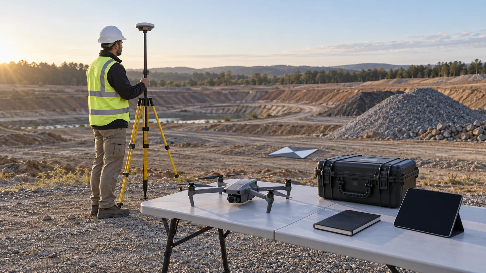
For dimensions used in engineering, request the units, coordinate reference,
scaling method, calibration information, and comparisons with independent
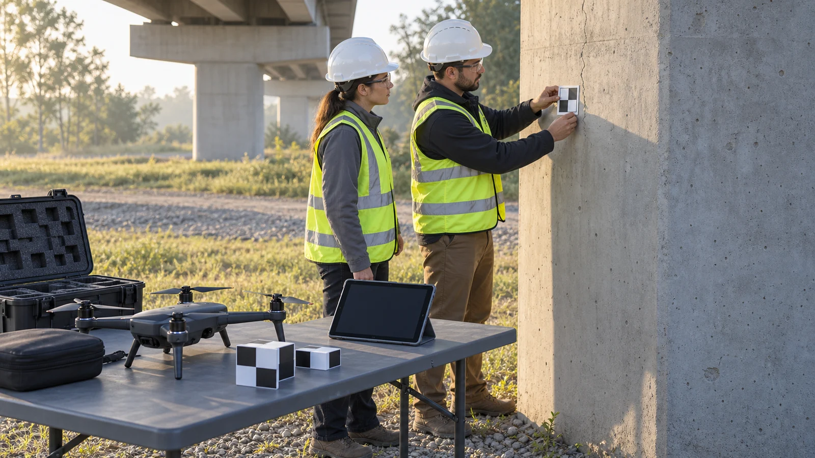
reference measurements. Keep those checks separate from the points used to fit
the model. Agree in advance which dimensions require checking and how
discrepancies will be reported. A model that is adequate for locating a spall
may be inadequate for measuring a small change between inspection dates.
From inspection brief to engineering handoff
The following sequence is a proposed commissioning approach, informed by the
inspection and calibration research above. Adapt it to the bridge owner's
procedures and the responsible inspection team's judgment.
- Define the questions. Identify whether the job is visual documentation,
investigation of known defects, change comparison, or support for a wider
inspection. Name the engineer or inspector who will decide whether the
evidence is sufficient.
- Supply the bridge context. Provide available drawings, bridge and element
identifiers, previous reports, known defects, priority locations, and a clear
convention for span, girder, and face numbering. Record missing drawings
instead of guessing geometry.
- Allocate each task to a method. Mark the surfaces proposed for drone
capture, the locations requiring another access method, and the observations
needing contact or specialist testing. Include launch access, traffic or rail
coordination, water conditions, lighting, and recovery constraints.
- Prove a representative capture. Let the inspection reviewer assess
original files from a difficult area before the crew repeats the approach
across the bridge. Review current conditions rather than assuming a previous
mission remains suitable.
- Check coverage in the field. Compare usable images with the agreed
element list before demobilizing. Log missed views and recapture needs. FHWA
describes an inspection team reviewing images directly from the aircraft's
memory card in the field in its
effective-practices report.
- Deliver observations with their limits. Connect each finding to a
component and original image. Separate observed conditions, measured
dimensions, suspected defects, and confirmed conclusions. Agree on an
immediate escalation route for potentially urgent findings rather than
waiting for the final report.
For repeat inspections, retain the element naming, reference system, and useful
viewpoints. Record changes in camera configuration, capture conditions, and
processing. A comparison needs enough context to distinguish a changed structure
from a changed representation of it.
Specify deliverables that can be checked
The table is a proposed buyer specification, not a mandatory reporting standard.
It translates the FHWA inspection practices, National Academies access findings,
and USGS calibration guidance cited above into reviewable outputs. The
quantities and tolerances should be agreed for the actual project.
Scroll horizontally to compare all columns.
Keep the coverage denominator honest. For example, if a scope contains 120
explicitly defined surface views and 108 have usable images, the illustrative
completion figure is 108 ÷ 120 × 100 = 90%. It does not mean 90% of defects were
detected, and the missing 12 views could contain the highest-priority locations.
Report those locations individually rather than hiding them inside a percentage.
Agree on delivery formats and retention before capture. Ask for a sample image
folder, finding register, and model export that your team can open. A hosted
viewer can help review, but it should not be the only agreed means of retrieving
the records needed for future inspections.
Questions to settle before commissioning a survey
Use the proposed scope to compare service providers or an internal program. The
most useful questions concern the work that remains after the flight:
- Which exact surfaces will the proposed aircraft and camera fail to see, and
how will those gaps be covered?
- Can the crew demonstrate readable detail in our darkest or most restricted
representative location?
- Which quantities will be measured, what error is acceptable, and what
independent references will check them?
- Who interprets indications, confirms defects, and accepts the inspection
evidence?
- What circumstances trigger recapture, another access method, or an urgent
notification?
- What original data and exports will we receive, and can we retain and use them
without continued viewer access?
- Does the proposal include planning, traffic coordination, processing,
inspection review, repeat visits, and remaining hands-on work?
For an accessible bridge where conventional inspection already answers the
questions efficiently, adding a drone may bring little practical benefit. For
difficult visual access, a drone can be a useful part of the inspection when its
deliverables replace a defined collection task and its omissions have a workable
follow-up plan. Commission that complete workflow, with the receiving inspection
team involved from the start.
Source notes
- National Academies, Uncrewed Aerial Systems Applications for Bridge Inspections, Chapter 2 (2024):
institutional research review covering sensor uses, access constraints, and
defect visibility.
- National Academies, Chapter 3: Findings and Applications (2024):
field research on aircraft configurations, girder access, stability, and
camera viewpoints.
- FHWA, Effective Practices for Routine Bridge Inspections Using Unmanned Aerial Systems (2021):
government case-based guidance on field review, thermal limitations, and model
uses.
- FHWA, Controlled-Environment Testing of UAS Digital Camera Sensor Specifications and Operational Parameters (2021):
government technical research on image quality under specified test
conditions.
- USGS, Guidelines for Calibration of Uncrewed Aircraft Systems Imagery (2023):
scientific guidance on calibration, geometric accuracy, and metadata.
- FAA, Part 107 Waivers:
current U.S. operational-waiver guidance, including visual line of sight and
operations over moving vehicles.
Last checked: September 6, 2026.