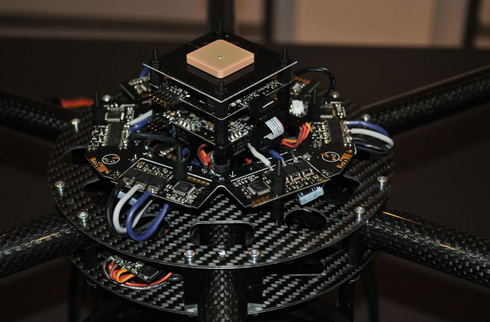
On this page
The role of each layer
The words IMU, AHRS, INS, flight controller, and autopilot are sometimes used as
if they name interchangeable boxes. They describe different functions, even when
one circuit board or software package performs several of them.
Scroll horizontally to compare all columns.
The
VectorNav inertial-sensor primer
uses a useful output-based distinction: an IMU supplies sensor measurements, an
AHRS supplies attitude, and an INS supplies position, velocity, and attitude.
Vendor packaging varies, so the output contract matters more than the label on
the enclosure.
The dedicated
IMU, AHRS, and INS comparison turns those
output differences into purchasing and interface questions.
NASA's
integrated UAS communications, navigation, and surveillance architecture
similarly separates navigation sources, inertial propagation, updates, and
feedback from vehicle-management functions. It is a research architecture, not a
required layout for every commercial drone, but the functional boundaries are
useful when assigning requirements and failure effects.
How measurements become a vehicle state
An accelerometer does not directly report vehicle acceleration in an earth-fixed
frame. It reports specific force along its own sensing axes. A gyroscope reports
angular rate about its axes. Before a controller can use those measurements, the
system must know the sensor orientation, remove or estimate biases, account for
gravity, and integrate the result over time.
That process has two recurring parts:
- Propagate: use the IMU and a motion model to predict the next attitude,
velocity, position, sensor biases, and uncertainty.
- Update: compare that prediction with a new measurement such as GNSS
velocity, barometric height, a range observation, optical flow, or external
vision, then correct states that the measurement can observe.
The
Kalman-filter primer
describes this predict-and-update sequence and the accompanying covariance, or
estimated uncertainty. Commercial autopilots often use an extended Kalman filter
because attitude and vehicle motion are nonlinear. The specific filter is less
important to a buyer than its documented inputs, outputs, validity tests,
delayed-measurement handling, and failure behavior.
The estimator is also where apparently compatible sensors can disagree. A GNSS
position jump without a corresponding inertial acceleration should produce an
innovation, meaning a difference between the predicted and observed measurement.
A well-designed system tests that difference against its expected uncertainty
before accepting, down-weighting, or rejecting the observation. The same
principle applies to a disturbed magnetometer, a blocked range sensor, or a
pressure change that does not match other vertical-state evidence.
This is why sensor fusion does not mean averaging everything. A filter can only
make a defensible update when the measurement model, timing, noise assumptions,
coordinate frame, and validity checks fit the installed system.
Where the autopilot fits
In common drone usage, autopilot can mean the whole flight-control computer,
its software, or only the guidance and control functions. For an integration
review, separate at least four functions:
- state estimation determines where the aircraft is, how it is oriented, how
it is moving, and how uncertain those estimates are;
- guidance converts a mission objective or pilot input into a desired path,
speed, acceleration, or attitude;
- control compares desired and estimated motion, then calculates actuator
commands; and
- vehicle and mission management selects modes, enforces limits, monitors
health, and invokes contingencies.
PX4's official
EKF2 navigation documentation
shows the estimator producing attitude, velocity, position, inertial-sensor
bias, magnetic-field, wind, and terrain states. Those estimates are adjusted for
the IMU's offset from the vehicle frame before being sent to control loops. That
is one documented implementation, not a universal autopilot design.
A controller closes loops at different levels. A fast inner loop may stabilize
angular rate. An attitude loop commands a desired orientation. Velocity and
position loops sit farther outside and depend on more navigation inputs. This
nesting explains why a vehicle can remain attitude-stable after losing global
position while no longer being able to hold a point on the map.
Programmed flight does not change these boundaries. The
difference between automation and autonomy
is about decision authority, not whether the software contains an estimator or
flies a route without continuous stick input.
Why update rate and latency are different
An IMU may produce hundreds or thousands of samples per second while GNSS may
update far less often. The
GNSS-aided INS explanation
notes that inertial propagation can bridge the interval between GNSS updates.
That does not make the slower source unimportant. GNSS provides an external
reference that constrains growing inertial position and velocity errors.
Four timing properties should be specified separately:
- sample rate: how often a sensor makes a measurement;
- output rate: how often a device publishes data;
- latency: how long data take to reach the point of use; and
- time accuracy: how closely the timestamp represents when the measurement
was valid.
A high output rate can simply repeat an old result. A low-latency measurement
without an accurate timestamp can still be fused at the wrong point in the
aircraft's motion. Variable latency, or jitter, can be harder to compensate than
a stable known delay.
PX4 documents a delayed fusion horizon and per-sensor delay parameters so that
measurements can be applied at their time of validity, followed by propagation
to the current control time. That implementation illustrates the integration
requirement: buffering and time alignment must be designed, configured, and
verified, not inferred from a bus data rate.
The controller has its own schedule, computation time, command latency, and
actuator response. End-to-end phase delay can reduce stability margin even when
every component meets an individual update-rate claim. Test timing from physical
motion through sensing, estimation, control, output, and actuator response.
Initialization and calibration
An estimator needs a credible initial state before its outputs can support all
flight modes. Depending on the architecture, initialization may include:
- stationary gyro-bias estimation;
- accelerometer and gyroscope scale, offset, and axis calibration;
- tilt alignment using the gravity direction;
- heading alignment from a magnetometer, dual antennas, motion, or another
reference;
- GNSS position, velocity, time, and quality checks;
- barometer or range-reference initialization;
- sensor-to-airframe orientation and lever-arm parameters; and
- estimator convergence and preflight health checks.
The
AHRS explanation
shows why each reference has limits. Gyro integration drifts.
Accelerometer-based tilt assumes the gravity vector can be distinguished from
vehicle acceleration. Magnetic heading is vulnerable to ferrous material and
electrical currents near the sensor. Calibration can compensate repeatable
installed effects, but not every disturbance the aircraft encounters.
Factory calibration and installed-system calibration answer different questions.
A calibrated IMU can still be mounted at the wrong orientation, exposed to
propeller vibration outside the qualified condition, heated differently from the
calibration profile, or placed far enough from the defined vehicle reference
point to make lever-arm effects material.
The FAA's active
AC 20-138D
is guidance for airworthiness approval of aircraft positioning and navigation
systems, not a small-drone shopping standard. Its distinction between equipment
capability and installed limitations is nevertheless important: a component
specification does not prove performance after antenna placement, wiring,
software, calibration, and airframe effects are introduced.
What changes without GNSS
GNSS loss removes one aiding source, not necessarily the entire IMU, attitude
solution, or control system. The immediate result depends on which states remain
observable from other sensors and which flight modes require global position.
An estimator may continue propagating attitude, velocity, and position from the
IMU. Attitude can remain useful longer than horizontal position because position
depends on integrating acceleration twice. Small attitude, accelerometer-bias,
and timing errors can therefore produce rapidly growing velocity and position
error. Alternative observations such as optical flow, visual odometry, radar,
terrain-relative measurements, or a trusted external position source can
constrain some states if the installed system supports and validates them.
The autopilot should not silently treat a dead-reckoned global position as
equivalent to a fully aided solution. It needs defined uncertainty limits,
mode-availability rules, operator indications, and a transition when the state
no longer supports the requested function. Position hold and return-to-home
depend on position, velocity, heading, route, destination, and sufficient
control authority. Losing or distrusting any required input can change what is
safe or even possible.
GNSS degradation is not identical to total loss. Plausible but wrong data can be
harder to detect than missing data because the filter must decide whether the
measurement or its prediction is wrong. The
GNSS-aided inertial navigation guide
examines that measurement and estimator boundary, while
the GNSS-loss operating guide follows the state,
mode, contingency, and recovery transitions.
The dedicated
UAS lost-link procedure guide addresses
command-and-control loss. Navigation degradation is a different failure, even
when both events eventually trigger a mode change.
Common architecture mistakes
Treating the IMU as the navigation answer
The IMU is the high-rate measurement source. Position, velocity, attitude, bias,
uncertainty, and validity are estimated outputs. A data sheet for the sensor
cannot establish the complete navigation performance.
Treating GNSS as the flight controller
GNSS supplies navigation observations. It does not stabilize the aircraft,
interpret a mission, command actuators, detect obstacles, or decide which
failure response is appropriate.
Treating AHRS, INS, and autopilot as fixed hardware boundaries
A flight computer may implement AHRS, INS, guidance, and control in software,
while another architecture uses a separate aided-INS unit. Procurement language
should name inputs, outputs, interfaces, rates, frames, validity states, and
responsibility instead of assuming the product label closes the boundary.
Treating sensor redundancy as estimator redundancy
Two IMUs on one board can protect against some sensor failures while sharing
power, clock, thermal, vibration, processor, software, and mounting risks. A
second estimator can compare solutions, but only if the selection and failure
logic are defined. Redundancy claims need a common-cause analysis and observed
failover evidence.
Treating a clean bench test as installed evidence
Propeller vibration, motor current, magnetic materials, GNSS antenna masking,
radio emissions, temperature gradients, cable timing, and structural flex are
installation effects. The
payload integration interface gate
provides a broader method for closing physical, electrical, data, timing,
environmental, control, and verification boundaries.
Questions for an operator or integrator
Ask for answers tied to the exact hardware, software, configuration, and
operating envelope:
- Which sensors are present, which estimator consumes each one, and which
vehicle states does each measurement make observable?
- What are the defined coordinate frames, axis conventions, mounting rotations,
lever arms, timestamps, and clock sources?
- What sample rate, output rate, fixed delay, jitter, and data-age limit apply
at the estimator and controller inputs?
- Which biases and calibration terms are factory-set, estimated in operation,
or calibrated after installation?
- How are inconsistent, stale, saturated, clipped, or missing measurements
detected and reported?
- Which control modes require attitude, local position, global position,
velocity, heading, height, or terrain states?
- What happens when each required state crosses its uncertainty or validity
limit, and what does the operator see?
- What redundancy is genuinely independent, and which power, clock, processor,
mounting, software, or environmental causes remain shared?
- Which logs preserve raw measurements, estimator innovations, uncertainty,
resets, mode changes, control commands, and configuration?
- Which analysis, simulation, bench, hardware-in-the-loop, and controlled
flight evidence applies to the installed configuration?
When the remaining decision is the measurement component itself, the
commercial UAS IMU selection guide
maps aircraft requirements to sensor specifications and installed evidence.
The
UAS command-and-control interface guide
uses the same end-to-end discipline for authority and message paths. Navigation
needs an equally explicit contract between sensor measurement, state estimate,
mode logic, controller, actuator, and operator display.
The useful system boundary
The most useful boundary is the closed loop, not the box. Physical motion is
measured, measurements are aligned and fused into a state with uncertainty,
guidance defines desired motion, control commands actuators, and the resulting
motion becomes the next measurement. Health and contingency logic supervise
every transition.
That model makes purchasing and integration questions concrete. It shows which
component provides evidence, which software owns an estimate or decision, and
which failure removes a measurement, a state, a mode, or control itself.
Frequently asked questions
Can a drone fly with an IMU but no GNSS?
It can remain controllable if its attitude and required height states remain
valid and the selected mode does not require global position. Whether it can
hold position, follow a route, or return depends on other aiding sensors,
estimator limits, vehicle configuration, and how quickly unaided errors grow.
Does every autopilot contain an AHRS or INS?
Most practical drone flight-control systems need an attitude estimate, but the
packaging varies. The estimator may run on the main controller, inside a
separate navigation unit, or across both. Confirm the outputs and interface
boundary rather than relying on the product category.
Is a higher sensor update rate always better?
No. The rate must be high enough for the vehicle dynamics and filter design, but
timestamp accuracy, latency, jitter, noise, bandwidth, filtering, processor
load, and actuator response also matter. Repeating stale data at a high output
rate does not improve control.
Where do the barometer, magnetometer, and optical flow fit?
They are additional measurements used by the state estimator. A barometer can
aid height, a magnetometer can aid heading, and optical flow can aid motion
relative to a viewed surface. Their usefulness depends on calibration,
environment, geometry, timing, and the estimator's validity checks.